
What is OP2?
Open Platform Humanoid Project

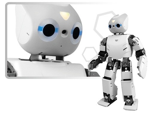
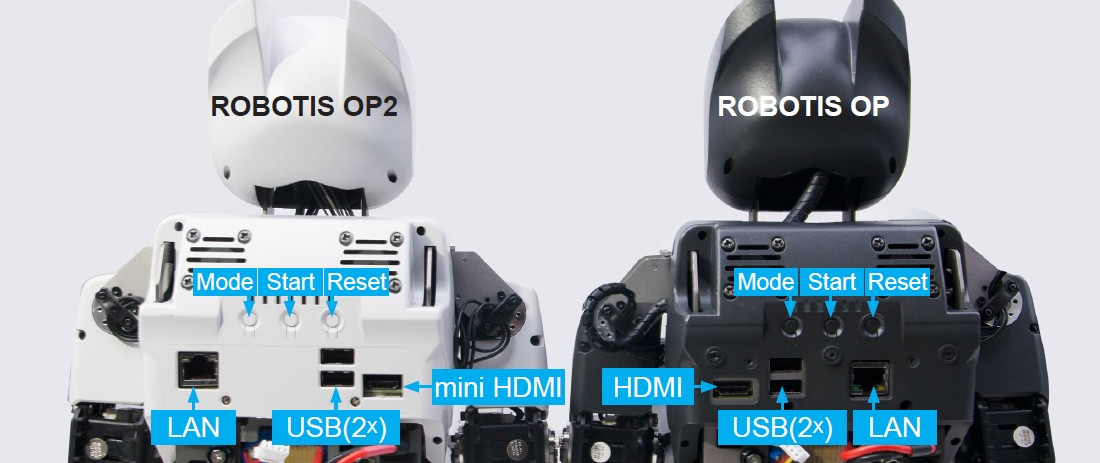
ROBOTIS OP2 (as known as “DARWIN 2” or DARWIN-OP2”) has been upgraded with greater computational performance compare to ROBOTIS OP (as known as “DARwIn-OP”).
Despite the change in name the robot may be colloquially still be called “Darwin”. The only major change comes from the upgrade in computational power.
When ROBOTIS OP was first released it was stated that it supported Windows OS.
This claim is, and remains, technically true. However, in practice installing Windows is impossible due to the 4GB cap of the embedded SSD from ROBOTIS OP’s PC.
The scant 4GB made difficult installing the later releases of Ubuntu and significant workaround was required to be able to install the later Linux releases.
ROBOTIS OP2 upgrade is aimed at eliminating the difficulties relating to computing from the previous generation.
You can now focus your efforts more into developing the robot and less on devoting resources for computing.


Here are some mechnamical differences
Reduced size of the management controller (CM-730 ⇨ CM-740)
| DARWIN OP | ROBOTIS OP2 | |
|---|---|---|
| CPU | Intel Atom Z530 @1.6GHz single core |
Intel Atom N2600 @1.6GHz dual core |
| RAM | 1GB DDR2 (fi xed capacity) |
up to 4GB DDR3 204-pin SO-DIMM module (user-replaceable) |
| Storage | 4GB NAND flash IDE100 (fixed capacity) |
half-size mSATA module (32GB) (user-replaceable) |
| LAN speed | 100 Mbps | 1 Gbps |
| Installable OS | Linux only (32-bit) | any Linux release (32-bit) any Windows release (32-bit) |
| wi-fi | 802.11g | 802.11n (2.4GHz-only) |
ROBOTIS OP2 is an affordable, miniature-humanoid-robot platform with advanced computational power, sophisticated sensors, high payload capacity, and dynamic motion ability to enable many exciting research and education activities.
Safety Information
CAUTION : ROBOTIS will not be responsible for any loss or damage whatsoever caused resulting from user’s negligence or misuse of the product.
Power On


Connect to OP2

System Block Diagram

Control Table Control Table consists of data regarding the current status and operation of CM-740. The user can control CM-740 by changing data of Control Table via Instruction packet.
EEPROM and RAM Data in RAM area is reset to initial values whenever the power is turned on while data in EEPROM area is kept once values are set even if the power is turned off.
Address Represents the location of data. To read from or write data to the control table the user should assign the correct address in the Instruction packet.
Access CM-740 has two kinds of data: Read-only data, used mainly for sensing, and read-and-write data used for driving.
Initial Value
In case of data in the EEPROM Area, the initial values on the right side of the below Control Table are the factory default settings.
In case of data in the RAM Area, the initial values on the right side of the following control table are the ones when the power is turned on.
Highest/Lowest Byte In the Control table, some data share the same name, but they are attached with (L) or (H) at the end of each name to distinguish the address. This data requires 16-bit, but it is divided into 8bit each for the addresses (low) and (high). These two addresses should be written with one Instruction Packet simutaneously.